
Every plant manager, quality assurance director, and process technician in the plastics manufacturing industry has faced the costly frustration of unexpected defect spikes. You load an approved polymer resin, blend in a standard masterbatch, lock the tooling clamps, and start an automated production cycle, only to find finished parts failing quality control due to warpage, flash, sink marks, or mottled color streaks. In high-volume plastics processing, throwing more clamp tonnage at a mold or randomly adjusting temperatures is an expensive, amateur mistake. Injection molding is a disciplined thermodynamic and rheological operation. Molten polymer is a non-Newtonian fluid whose viscosity, crystalline kinetics, and molecular orientation change dynamically across fractions of a second. Producing dimensionally stable, cosmetically flawless components requires full scientific control over your Injection Molding Parameters.
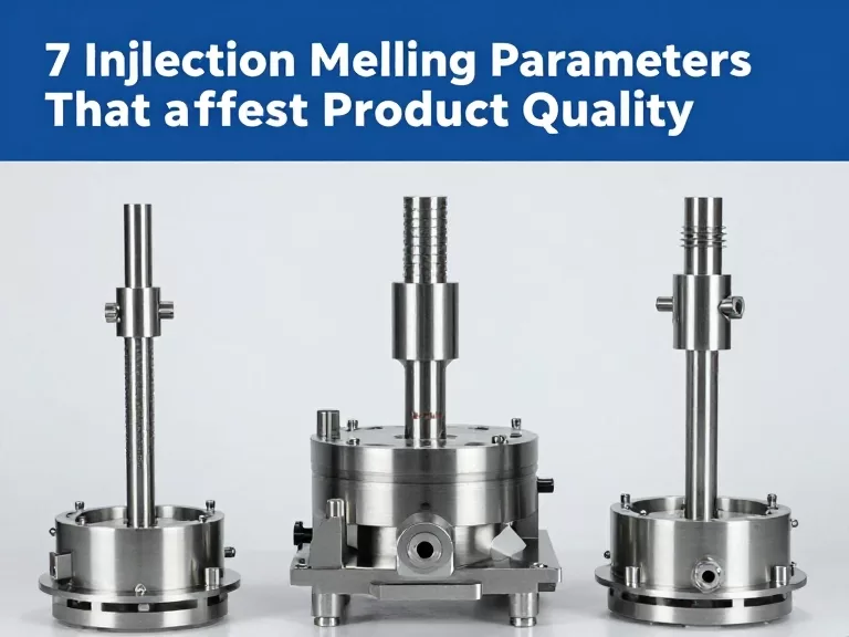
Mastering your Injection Molding Parameters is not about blindly copying the mold design sheet; it is about establishing a robust processing window that absorbs natural variances in ambient humidity, regrind percentages, and pigment dispersion. As a masterbatch compounding specialist and technical processing partner at Charming Masterbatch, we work directly with molding facilities worldwide running demanding resins. Here is our practitioner-grade evaluation of the 7 core Injection Molding Parameters that dictate product quality, explaining the underlying physics of each setting, how they interact, and how to calibrate them for maximum yield.
Quick Answer: The 7 Core Injection Molding Parameters for Flawless Quality
The seven decisive Injection Molding Parameters governing plastic part quality are: (1) Melt Temperature (controls polymer viscosity, molecular degradation, and thermal pigment stability); (2) Mold Temperature (dictates cooling rate, semi-crystalline morphology, surface gloss, and warpage); (3) Injection Velocity / Speed (governs shear thinning, gate vestige quality, and filling uniformity); (4) Switchover Point (V/P Transfer) (prevents cavity over-pressurization and eliminates flash or short shots); (5) Holding / Packing Pressure and Time (compensates for volumetric thermal shrinkage to eliminate sink marks and internal voids); (6) Cooling Time (ensures structural rigidity above heat deflection temperature prior to ejection); and (7) Back Pressure (provides homogeneous melt plasticization and thorough masterbatch pigment dispersion). Dialing in these seven parameters systematically using scientific molding principles eliminates up to 90% of chronic molding defects.
Article Directory
- Scientific Molding: Why Guessing Machine Settings Destroys Margin
- Quick Summary Table: The 7 Key Injection Molding Parameters
- In-Depth Analysis: The 7 Critical Injection Molding Parameters
- Material & Color Quality Spotlight: Charming Masterbatch
- Direct Parameter Comparison: Impact on Common Molding Defects
- Pros and Cons: Wide Processing Windows vs. Tight Scientific Control
- Who Should Adjust Parameters vs. When Tooling/Resin Must Change
- Costly Mistakes Technicians Make When Adjusting Parameters
- Essential Optimization Checklist: Establishing a Scientific Window
- Expert Manufacturing Verdict: The Sustainable Production Blueprint
- Frequently Asked Questions
- Authoritative References & Technical Standards
Scientific Molding: Why Guessing Machine Settings Destroys Margin
In traditional injection shops, machine setup is often treated like an art form passed down by senior operators. When a sink mark appears, an operator raises holding pressure; when flash appears on the parting line, someone lowers clamp tonnage or drops nozzle temperature. This reactive trial-and-error approach leads to unstable cycles, high scrap rates, and inconsistent part weights. In most professional situations, treating machine adjustments as isolated dials ignores the coupled physics of polymer processing.
Thermoplastics exhibit non-Newtonian, shear-thinning behavior: as you push molten plastic faster through a restrictive runner and gate, its apparent viscosity drops exponentially. A 10% change in injection speed alters melt temperature inside the cavity through shear heating, which in turn alters volumetric shrinkage, gate freeze time, and final part dimensions. Scientific molding decouples the process into distinct, repeatable stages: filling, packing, cooling, and plasticizing. By measuring and controlling physical plastic variables—rather than machine-specific setpoints—you establish an unshakeable process window. When setting up your Injection Molding Parameters, every adjustment must serve an intentional purpose within that decoupled framework.
Quick Summary Table: The 7 Key Injection Molding Parameters
| Molding Parameter | Primary Physical Function | Key Quality Metric Affected | Primary Risk of Setting Too High | Primary Risk of Setting Too Low |
|---|---|---|---|---|
| 1. Melt Temperature | Controls polymer viscosity and thermal energy | Flow length, tensile strength, color purity | Thermal degradation, flashing, burning | Short shots, high stress, poor weld lines |
| 2. Mold Temperature | Controls heat transfer rate and crystallization | Surface gloss, warpage, cycle time | Sticking, long cycles, thermal blistering | Dull gloss, severe internal stress, warpage |
| 3. Injection Speed | Determines shear rate during dynamic fill | Filling balance, jetting, burn marks | Jetting, gate blush, flash, shear burns | Hesitation lines, short shots, weak weld lines |
| 4. Switchover Point | Transitions from velocity to pressure control | Cavity peak pressure, tool protection | Over-packing, mold flashing, parting line wear | Premature freeze, sink marks, short shots |
| 5. Holding Pressure & Time | Compensates for volumetric resin shrinkage | Part weight, dimensional tolerance, sink marks | Over-packing gate area, ejection sticking | Sink marks, post-mold shrinkage, voids |
| 6. Cooling Time | Solidifies resin below Heat Deflection Temp | Ejection rigidity, warpage, total cycle cost | Unnecessary cycle time and margin loss | Part deformation, ejector pin push-through |
| 7. Back Pressure | Controls melt homogenization and screw shear | Masterbatch dispersion, melt density | Screw wear, resin drool, thermal degradation | Color streaking, entrapped air, density variance |
In-Depth Analysis: The 7 Critical Injection Molding Parameters
1. Melt Temperature (Barrel Temperature Profile)
Melt temperature is the actual thermal energy of the molten polymer as it exits the nozzle tip. It is established by the external ceramic heating bands along the barrel zones (feed, compression, metering, and nozzle) combined with the frictional shear generated by the rotating screw. Melt temperature dictates the thermodynamic viscosity curve of the resin. For commodity polyolefins like PP and PE, the window is relatively wide; for engineering polymers such as polybutylene terephthalate or technical vinyl blends, the thermal envelope is exceptionally narrow.
When working with specialized materials, such as understanding thermal processing in our guide on what is PBT masterbatch or reviewing heat limits in what is PVC masterbatch, maintaining precise barrel zoning is critical. If melt temperature is set too high, polymer chains undergo thermal scission, reducing molecular weight and causing severe embrittlement. Furthermore, organic pigments inside color concentrates can scorch, shifting target shades away from your master specification on a masterbatch color code chart. If melt temperature is too low, the resin exhibits excessive melt viscosity, requiring dangerous injection pressures that induce high residual molded-in stresses.
2. Mold Temperature
Mold temperature is governed by pressurized water or oil circulation units (MTCs) running through internal cooling channels within the tool steel. While melt temperature gets resin into the mold, mold temperature governs how that resin transitions from liquid to solid. In semi-crystalline polymers (such as PA, POM, PP, and PBT), mold temperature directly dictates the degree of crystallinity.
In our testing, running a cold mold on semi-crystalline resins yields a quick cycle time, but arrests crystal formation, leaving the part mechanically soft and prone to post-mold dimensional shrinkage when exposed to warm ambient environments. Conversely, a heated mold allows polymer chains to organize into tight crystalline spherulites, maximizing tensile modulus, chemical resistance, and surface gloss. For aesthetic parts, elevated mold temperatures keep the advancing flow front molten longer, forcing the plastic tightly against polished or textured cavity surfaces. However, differential cooling—where the core half runs hotter than the cavity half—is the number-one driver of severe part warpage and bowing.
3. Injection Speed (Velocity Profile)
Injection speed describes the forward velocity of the reciprocating screw during the initial cavity filling phase (typically the first 95% to 98% of the part volume). Under scientific molding principles, filling must be entirely velocity-controlled, independent of pressure limits. The machine should supply whatever hydraulic or electric pressure is required to maintain the programmed flow front velocity.
Because molten plastic is pseudoplastic, faster injection speeds induce shear thinning at the gate, lowering apparent viscosity and allowing intricate, thin-walled geometries to fill effortlessly. However, excessive velocity creates severe frictional shear heating. If the flow front accelerates violently through a restricted pin gate, shear temperatures can spike 30°C to 50°C above barrel setpoints, degrading UV stabilizers—such as those detailed in our report on UV masterbatch uses and benefits—and causing localized burning or gate blush. For thick-walled parts, a profiled, multi-stage injection speed curve (slow through the gate, fast through the main cavity body, slow at end-of-fill) is required to prevent cosmetic jetting and air dieseling.
4. Switchover Point (Velocity-to-Pressure Transfer)
The switchover point, or V/P transfer position, is the precise linear screw position where the machine terminates dynamic high-speed injection and switches to static holding pressure. In modern processing, this is the single most critical threshold protecting both part quality and mold steel longevity.
In most professional situations, we recommend setting switchover at the exact moment the mold cavity is 95% to 98% volumetrically full. You can verify this by running a short-shot study with holding pressure turned completely off: the resulting part should look like a complete component with only the absolute farthest edges or thick ribs slightly unfilled. If switchover occurs too early, the machine attempts to pack out the remaining cavity volume under low-speed pressure control, causing hesitation marks, short shots, and weak weld lines. If switchover occurs too late, the high-speed forward screw slams into a completely packed cavity, generating catastrophic hydraulic pressure spikes that flash the mold, crush parting line vents, and cause tool wear.
5. Holding Pressure and Holding Time
Thermoplastics shrink as they cool from melt state to solid ambient temperature—semi-crystalline resins can shrink between 1.5% and 2.5% volumetrically. The purpose of the holding phase (also referred to as the pack-and-hold stage) is to force additional molten plastic into the cavity to compensate for thermal volumetric contraction as the part solidifies against the cold steel walls.
Holding pressure must be set as a secondary step after filling is locked. The holding pressure level dictates final part weight and dimensional tolerances. If holding pressure is too low, the center of thick sections will pull inward as they cool, forming unsightly sink marks or internal vacuum voids. To determine optimum holding time, process engineers must run a Gate Freeze Study (gate seal test): weigh consecutive parts as holding time is increased by one-second increments. The moment part weight plateaus and stops increasing, the gate has frozen solid. Holding pressure applied after gate freeze is wasted energy and adds zero value to part density; cutting holding time to the exact gate freeze point maximizes production efficiency.
6. Cooling Time
Cooling time represents the largest single block of the overall injection molding cycle time, typically accounting for 60% to 80% of total cycle duration. From an economic standpoint, cooling time is where machine hour profitability is determined. Physically, cooling time begins the moment injection initiates, but on machine controllers, the cooling timer governs how long the closed tool remains clamped after holding pressure terminates while the screw recovers for the next shot.
The cooling timer must run long enough for the thickest wall section of the part to drop below its Heat Deflection Temperature (HDT) or vicat softening point. If a part is ejected while its core is still soft and molten, the mechanical force of the ejector pins will punch white stress marks into the plastic or warp the part during free-air cooling. However, running excessive cooling time to compensate for inadequate mold cooling channel design simply burns working capital and drives up unit costs, especially when processing high-volume filled compounds formulated according to our what is filler masterbatch technical guide.
7. Back Pressure and Screw Recovery Speed
Back pressure is the controlled hydraulic or mechanical resistance exerted against the reciprocating screw as it rotates backward to prepare the next dose of molten resin. Rather than allowing the screw to freely slide back as pellets melt, back pressure restricts backward movement, forcing the flight channels of the screw to work against the viscous melt under intense mechanical shear.
For processors utilizing color concentrates, back pressure is the master key to aesthetic quality. Without adequate back pressure, pellets slide along the barrel with laminar flow, resulting in un-melted masterbatch cores and visible marble swirls in the finished part. Applying proper back pressure (typically 5 to 15 bar hydraulic, or 50 to 150 bar specific melt pressure) generates frictional work that crushes pigment agglomerates and distributes colorants evenly throughout the polymer matrix. When working with high-pigment systems, such as those evaluated in our black masterbatch suppliers guide or formulated according to our masterbatch composition guide, dialing in back pressure ensures full color saturation without buying expensive specialized static mixing nozzles.
Material & Processing Excellence: Charming Masterbatch Solutions
Achieving stable, repeatable Injection Molding Parameters requires raw materials that exhibit absolute batch-to-batch consistency. Operating advanced twin-screw compounding extruders imported directly from Germany, Charming Masterbatch combines decades of processing expertise with cutting-edge pigment dispersion technology to support high-precision molding operations worldwide.
| Compounding Technology | High-torque German twin-screw extruder lines ensuring microscopic pigment de-agglomeration |
| Product Formulations | Custom color masterbatch, high-opacity black/white concentrates, and specialized functional additives (UV, anti-static, slip, flame retardant) |
| Global Market Presence | Trusted across China and exported to over 18 international markets including Europe, South America, Southeast Asia, and North Africa |
| Engineering Support | Direct factory technical assistance, individual color development, rheological matching, and injection troubleshooting services |
Procurement & Processing Advice: Material inconsistency forces operators to constantly tweak machine settings. Eliminate parameter drift by sourcing certified concentrates from vetted masterbatch suppliers worldwide, review current commodity indices in our plastic masterbatch price per ton 2026 analysis, or select verified shades using our plastic color chart with codes.
Direct Parameter Comparison: Impact on Common Molding Defects
| Visual / Structural Defect | Primary Parameter Culprit | Secondary Parameter Culprit | Root Physical Mechanism | Recommended Corrective Action |
|---|---|---|---|---|
| Sink Marks & Voids | Holding Pressure too low | Holding Time too short (premature freeze) | Volumetric shrinkage uncompensated in thick ribs | Increase holding pressure; run gate freeze study to extend pack time |
| Parting Line Flash | Switchover Point too late | Holding Pressure too high | Cavity peak pressure exceeds machine clamp tonnage | Move switchover position back; verify 95% volumetric fill on short shot |
| Part Warpage & Bowing | Mold Temperature differential | Cooling Time too short | Asymmetrical shrinkage rates across core and cavity | Balance core/cavity water temperatures; increase cooling cycle duration |
| Short Shots (Incomplete Fill) | Injection Velocity too slow | Melt Temperature too low | Flow front freezes off before reaching end-of-fill | Increase injection speed; raise barrel temperatures in metering zone |
| Color Streaking / Swirls | Back Pressure too low | Melt Temperature too low for carrier | Incomplete mechanical shear and pigment dispersion | Raise back pressure by 20–30 bar; match masterbatch carrier MFI |
| Burn Marks (Dieseling) | Injection Velocity too fast at end-of-fill | Clamping Force over-compression | Trapped air cannot escape vents and combusts under pressure | Profile injection speed to slow down at final 5%; clean tool vents |
Pros and Cons: Wide Processing Windows vs. Tight Scientific Control
| Processing Methodology | Practical Factory Advantages (Pros) | Operational Realities & Drawbacks (Cons) |
|---|---|---|
| Decoupled Scientific Parameter Control (Locked V/P transfer, in-cavity sensor monitoring) | Scrap rates consistently maintained below 1.5%. Tooling wear and parting line damage virtually eliminated. Predictable cycle times enable precise job costing. Process easily transferred across identical tonnage presses. Immediate detection of raw resin viscosity shifts. | Requires upfront engineering time for gate freeze and viscosity curves. Demands trained technicians who understand polymer physics. Requires modern machines with reliable closed-loop controllers. |
| Traditional Trial-and-Error Dial Tuning (Operator tweaking settings based on visual parts) | Immediate machine startup without initial engineering studies. Low initial setup labor for quick, non-critical short runs. Requires zero advanced in-cavity instrumentation. | Scrap rates fluctuate wildly between 5% and 15%. High risk of mold flashing and tool damage from pressure spikes. Process drifts whenever day/night ambient temperatures shift. Frequent warranty returns due to latent stress cracking. |
Who Should Adjust Parameters vs. When Tooling/Resin Must Change
A fundamental discipline in lean plastics manufacturing is knowing when a defect can be solved by tuning Injection Molding Parameters and when tweaking parameters is merely masking an un-moldable part design or inadequate tool steel geometry.
When You Should Optimize Injection Molding Parameters:
- Eliminating Cosmetic Surface Blemishes: Sink marks on shallow ribs, minor weld lines, flow hesitation marks, gate blush, and color swirls are almost always solvable through systematic profiling of injection speed, holding pressure, and back pressure.
- Compensating for Minor Lot-to-Lot Resin Variance: Even virgin resins from tier-one petrochemical refiners experience slight Melt Flow Index (MFI) shifts between railcars. Adjusting injection velocity or barrel zone temperatures re-establishes optimal shear rates to absorb these shifts.
- Reducing Excessive Cycle Time: Optimizing holding time via gate seal testing and balancing mold water Reynolds numbers routinely shaves 15% to 30% off bloated cycles without compromising dimensions.
When Parameters Cannot Fix the Problem (Tooling or Resin Failure):
- Severe Structural Thickness Transitions: If a product designer mounts a 6mm solid boss directly onto a 1.5mm nominal wall, no amount of holding pressure will eliminate sink marks. The thin wall freezes off immediately, isolating the molten mass in the thick boss. The tool steel must be modified with coring pins.
- Inadequate Mold Venting: If burn marks occur at the dead ends of ribs because toolmakers failed to grind 0.02mm to 0.04mm parting line vents, slowing injection speed to a crawl is a terrible workaround that ruins cycle efficiency. The mold must be pulled and vented.
- Resin & Carrier Incompatibility: If an operator uses a general-purpose polystyrene (GPPS) color masterbatch inside a polyamide-6 (PA6) base resin, no adjustment of back pressure will force those polymers to bond chemically. The carriers will delaminate, causing the finished part to peel like onion skin. When sourcing black concentrates, review compatibility standards from verified black masterbatch manufacturers 2025.
Costly Mistakes Technicians Make When Adjusting Parameters
Factory Floor Advisory: The “Multi-Dial Adjustment” Disaster
The most common mistake on processing floors is changing multiple Injection Molding Parameters simultaneously. When a technician encounters a warped part with flash, they simultaneously increase cooling time, lower holding pressure, and reduce barrel temperature. If the next shot looks better, nobody knows which variable solved the issue, and three new latent defects are introduced into the run. Always adjust one single parameter at a time, allow the machine to run 15 to 20 cycles to reach thermal and mechanical equilibrium, and inspect part weight before making another change.
- Packing Out Parts Using Injection Velocity Instead of Holding Pressure: Running the screw at high speed all the way to 99% of travel before switching to holding pressure. This eliminates the safety buffer. The moment a slightly stiffer batch of resin enters the barrel, the machine spikes past maximum pressure limits, flashing the mold and crushing parting lines.
- Ignoring Real-World Melt Temperature: Relying solely on the thermocouple digital displays on the machine control cabinet. Thermocouples measure the steel barrel wall, not the moving plastic inside. Frictional shear from screw rotation often pushes actual melt temperatures 10°C to 25°C higher than setpoints. Always use a calibrated digital pyrometer to take an insulated purge puddle temperature measurement.
- Setting Holding Time Past Gate Freeze: Running holding pressure for twelve seconds when the gate freezes solid at five seconds. Those extra seven seconds of holding pressure apply zero packing force to the part, but consume hydraulic energy and extend cycle times by thousands of cumulative hours across annual production.
- Neglecting Reynolds Numbers in Water Channels: Running low-velocity laminar water through mold cooling circuits. To extract heat rapidly and uniformly, cooling water must flow with turbulent flow, requiring a Reynolds number exceeding 4,000. Operating with laminar water flow creates hot spots that induce severe part warpage regardless of how long you set the cooling timer.
Essential Optimization Checklist: Establishing a Scientific Window
Before launching an automated production run, process engineers should systematically establish and document their Injection Molding Parameters using this four-stage validation sequence:
Stage 1: Generate the Dynamic Rheology Curve (Viscosity vs. Shear Rate)
Turn off holding pressure and set switchover at 95% volume. Vary injection speed from 10% to 100% in stepped increments, recording peak hydraulic pressure and fill time. Calculate relative viscosity ($Viscosity \propto Pressure \times Time$). Plot the curve: identify the flat, stable plateau where changes in injection speed produce minimal changes in viscosity. Set your production injection velocity within this stable processing window.
Stage 2: Lock the 95% Volumetric Fill & Switchover Position
With holding pressure still zeroed, adjust the injection screw forward cutoff until the part is 95% to 98% visually complete. The flow front should be hesitation-free with uniform, un-flashed edges. Lock this position as your permanent V/P transfer setpoint.
Stage 3: Run the Gate Seal (Weight vs. Holding Time) Study
Activate holding pressure at roughly 50% of peak injection pressure. Start holding time at two seconds and weigh parts on an analytical balance sensitive to 0.01 grams. Increase holding time by one-second intervals. Plot part weight against holding time. When part weight stabilizes, add one second as a safety margin and lock that value as your holding time parameter.
Stage 4: Optimize Cooling Time and Thermal Balance
Adjust holding pressure magnitude up or down to achieve nominal part dimensions and eliminate sink marks. Once dimensions are verified, reduce cooling time incrementally until part ejection causes dimensional deflection or pin indentation. Add two seconds of safety time, balance cooling circuit flow to achieve turbulent flow ($Re > 4000$), and record the final master setup sheet.
Expert Manufacturing Verdict: The Sustainable Production Blueprint
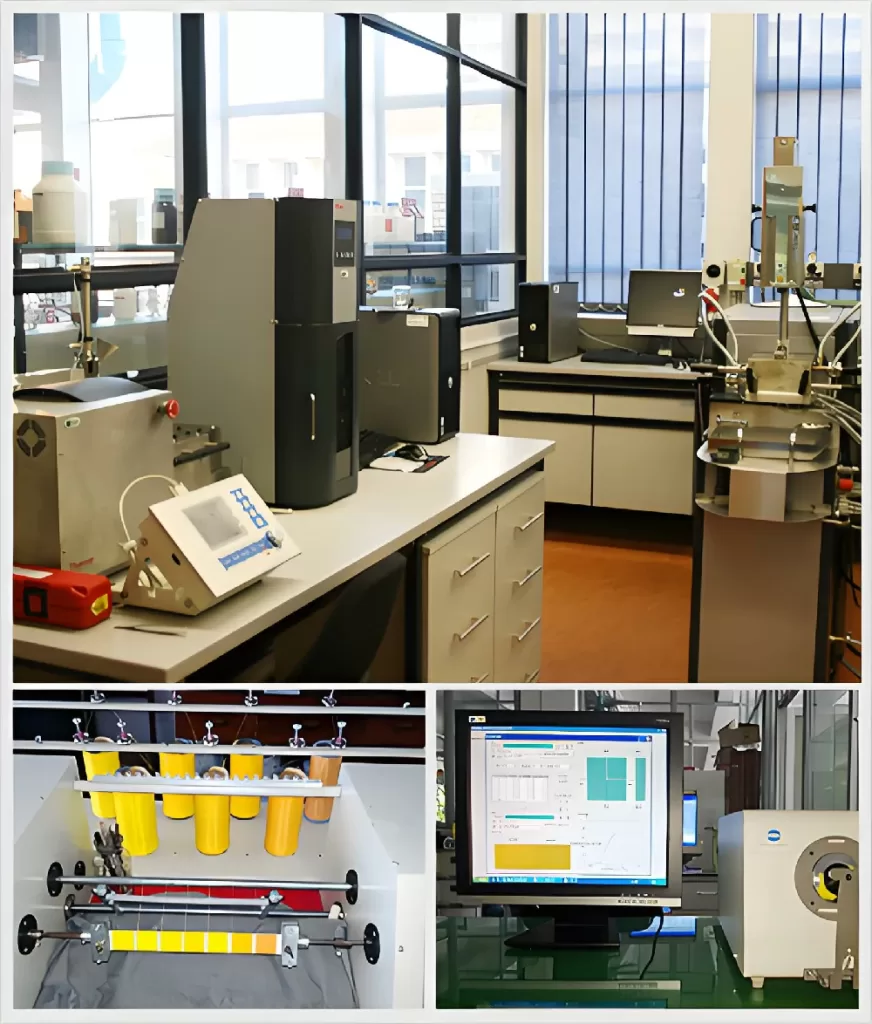
In our professional assessment across decades of polymer processing and color masterbatch manufacturing, managing Injection Molding Parameters is not about finding a magic setpoint; it is about respecting the coupled thermodynamics of polymer flow. High-efficiency injection molding requires an unyielding commitment to decoupled scientific processing, disciplined tooling maintenance, and raw material consistency.
Here is our practical recommendation for your production roadmap:
- Lock Down Your Decoupled Process: Stop adjusting fill speeds to solve sink marks. Use dynamic velocity control strictly to fill the first 95% of the cavity, and reserve holding pressure strictly to pack out volumetric shrinkage until gate freeze.
- Audit Temperatures with Physical Pyrometers: Never trust barrel readouts alone. Measure your actual purge temperature, monitor core and cavity steel temperatures with surface probes, and ensure turbulent water flow through all cooling lines to prevent warpage.
- Use Back Pressure Strategically for Color Homogeneity: When running high-load colorants or functional masterbatches, do not increase barrel heat to blend colors. Raise your back pressure to generate mechanical shear, breaking down pigment clusters cleanly without causing thermal polymer degradation.
- Eliminate Material Variables at the Source: The best processing window in the world cannot compensate for erratic raw materials. Partner with an established, asset-backed compounding manufacturer like Charming Masterbatch. Sourcing high-dispersion concentrates compounded on German twin-screw extruders guarantees that your rheological melt behavior, color saturation, and additive distribution remain stable from the first shot to the millionth.
Frequently Asked Questions
What are the most critical injection molding parameters affecting part quality?
The seven decisive injection molding parameters are melt temperature, mold temperature, injection velocity, holding pressure and time, switchover point (V/P transfer), cooling time, and back pressure. Controlling these variables prevents structural defects like sink marks, flash, warpage, and color streaking.
How does back pressure affect color masterbatch dispersion in injection molding?
Back pressure forces the rotating screw to work harder against molten resin during plasticization. Increasing back pressure increases shear stress, which breaks up agglomerated pigment particles and ensures homogeneous blending of color masterbatch into base resin, eliminating visible color swirls and streaks.
What happens if the switchover point (V/P transfer) is set incorrectly?
If switchover occurs too early, the machine drops from velocity control to pressure control before the cavity is filled, resulting in short shots and flow lines. If switchover occurs too late, the high-speed injection fills 100 percent of the cavity under velocity control, causing extreme pressure spikes, flashing along the parting line, and mold damage.
Why does mold temperature have a direct impact on part warpage?
Differential mold temperatures between core and cavity halves cause uneven cooling and non-uniform volumetric shrinkage across the part geometry. As one side solidifies and shrinks faster than the other, residual internal stresses pull and bow the finished component out of dimensional tolerance.
Authoritative References & Technical Standards
- Society of Plastics Engineers (SPE): Scientific Molding Principles and Injection Molding Division Technical Papers
- ASTM International: ASTM D3641 Standard Practice for Injection Molding Test Specimens of Thermoplastic Materials
- International Organization for Standardization: ISO 294-1 Plastics – Injection Moulding of Test Specimens of Thermoplastic Materials